Historical SAAB: An extract from Saab VIPS magazine No 5,1964. Translation compiled by Ray Beaufoy 2022-11-30.
New machinery has been installed at Saab-G in Gothenburg where cylinder-blocks for Saabs three cylinder, two-stroke engines are manufactured –The multi-task machinery has the ability to perform twenty-five different machining operations.
A total of 90 M.SEK, whereas 30 M.SEK over the last three years, has been invested in modernising the engine and gearbox production plant in Gothenburg.
These were the opening words from Saab´s director Svante Holm at a presentation for representatives and journalists from leading motoring organisations.
Svante Holm made a particular point of informing that despite forthcoming emissions legislation favouring modern 4-stroke engines, Saab did not have any immediate plans to stop production of their current two-stroke engine. Proof, he said, can be seen in the significant investments that the company had made in new machinery and workshops here in Gothenburg – 3 M.SEK alone being spent on cylinder-block production line which now includes a fully automatic transfer machine capable of effectively performing twenty-five different machining operations.
The new transfer machine has been specifically built to produce the Saab 2-stroke engine and is virtually impossible to convert to manufacturing four-stroke engines.
During the press conference Rolf Mellde, Saabs Engineering manager, explained that to rectify the excessive smoke and oil odour emitted from Saabs 2-stroke engine, development is ongoing to produce a new 2- stroke engine oil which, when mixed with fuel and burnt in the engine, produces less exhaust emissions.
Tenfold increase in production over ten years
It has now gone ten years since Saab started manufacturing engines and gearboxes in Gothenburg. In 1953, the workshop premises were purchased from Electrolux and engine production started the following year. At the time of acquisition, the factory floor covered an area of 16,000 m2 today it is 30,000 m2.
In 1954, a total of four thousand engine and gearbox units were produced – in 1963 this figure had increased almost tenfold. In November, this year we are anticipating an increase in production to 50,000 units.
This upward trend in production has been made possible by streamlining work routines and reducing labour costs. In 1954, a total of thirty-seven working hours were needed to produce a single drivetrain, today only 10.2 working hours are needed.
Currently we have 750 members of staff working here.
Workshop area completed
With modern machinery, an annual volume of 60,000 units can be achieved however above this figure larger new premises must be found.
Ongoing alterations to the existing premises include a new multi-storey parking lot, and a new 160 m long, three-storey manufacturing workshop which became operational earlier this year at a cost of SEK 10 M.SEK.
It is in these buildings where gearbox components are manufactured and where the complete gearbox is tested and fitted to the engine unit.
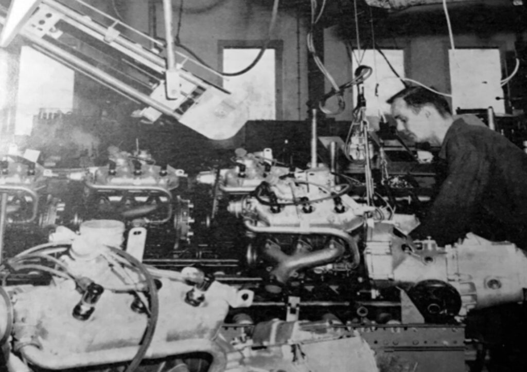
Manufacturing process
The manufacture of engines and gearboxes follow specific numerous procedures some of which can be seen in the photos below. Upon initial arrival at the factory, all raw materials and externally manufactured components are inspected and verified that they comply with Saabs design and manufacturing specifications. Even throughout production further quality checks are performed by employees at their individual work-stations – every sixth employee at Saab-G is responsible for performing some form of inspection process in their daily work schedule.
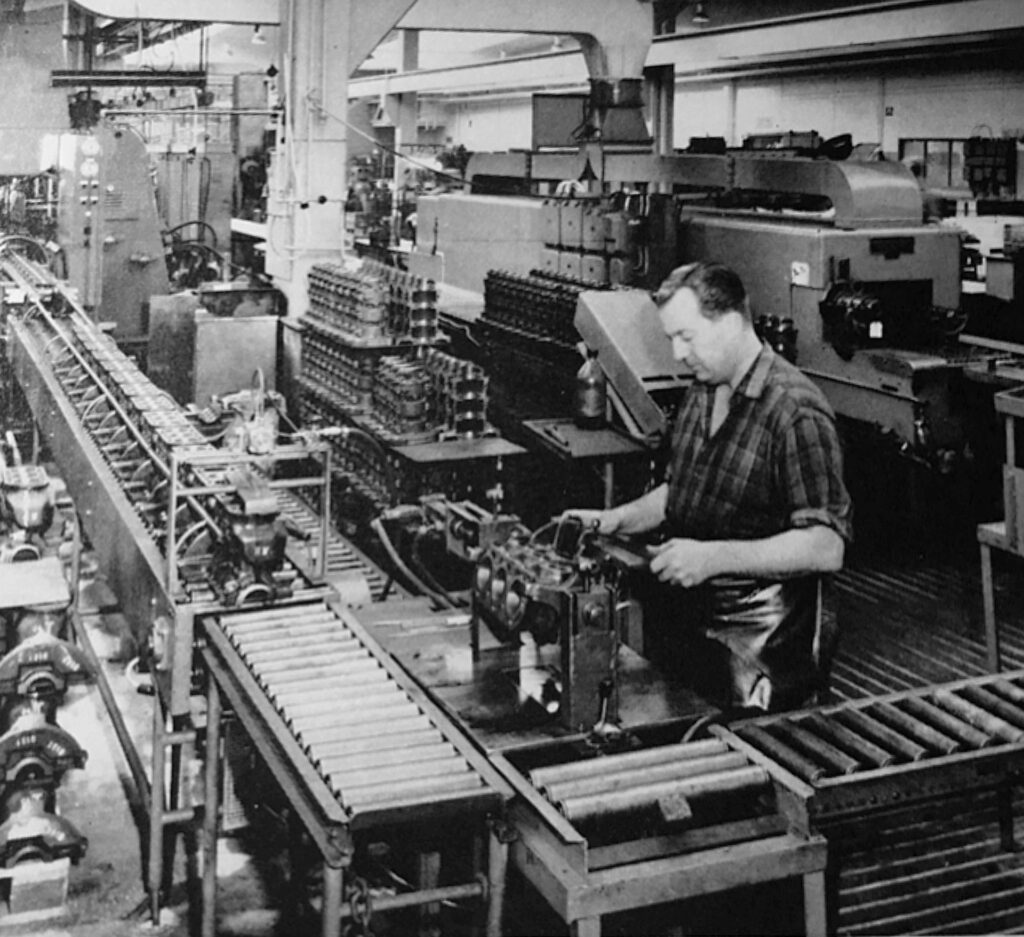
Progressive manufacturing
After components have been inspected, they are then stored until being released into the different production areas. Larger castings, such as gearbox covers, engine blocks and clutch housings, are all processed in special machine groups, so-called ´lines´. Once an operation has been completed roller conveyors transport components to the next operation.
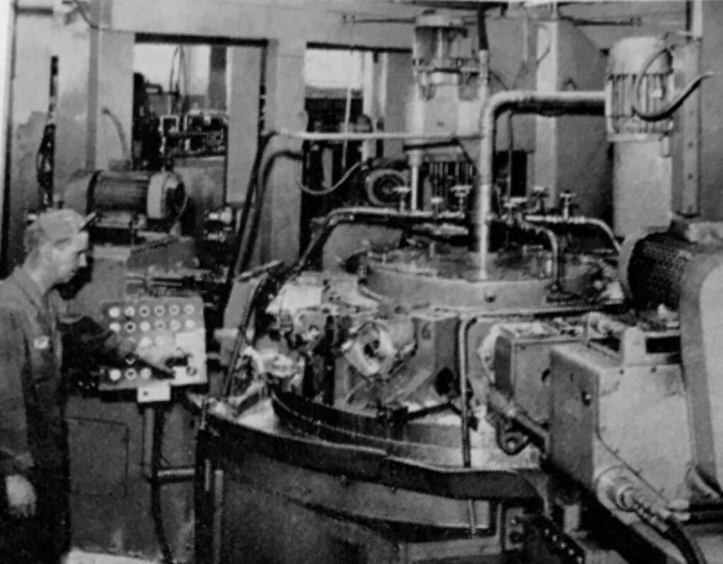
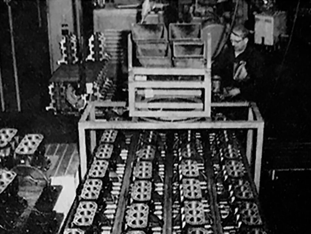
The longest production line is that of the engines cylinder-block and where the previously mentioned transfer machine performs twenty -five different operations with minimal manual intervention.
The man in Photo 3, standing alongside the transfer machine needs only to load the cylinder block into the machine, A further operator receives the completed cylinder-block prior to assembly with the engine’s crankcase sections.
In full production mode the transfer machine contains twenty-five cylinder-blocks in various phases of manufacture and where 127 different tools i.e., drills, reamers, dies and taps etc are used.
Four surfaces are planned flat, and seventy-five holes are drilled of which forty are internally threaded and eight are broach finished.
Once all optical checks have been made a finished cylinder block is fed out of the machine every 90 seconds.
Each unit is checked, and measurements recorded.
The length of time a cylinder block remains at every workstation is the same and timed to be in phase with the production of new cars rolling off the production line in Trollhättan.
During the complete manufacturing process random samples are taken from the production line and checked any adjustments to fixtures and tools are made if necessary.
Main bearings journals and cylinder bores are given special attention with precision drilling and honing of critical surfaces – each block is measured, and dimensions are individually recorded.
Cylinder block bores and pistons clearances etc.
For the engine to have the correct piston clearances – between piston and respective cylinder walls – it is necessary to accurately measure each cylinder bore and selection of an appropriate piston size. Cylinder bores are classed in separate groups with a tolerance range of 0,007 mm. Pistons, which are purchased ready for use, are classified in four groups.
Classification of the cylinder bores is done together with the final inspection of the cylinder block. A tightness check is also later performed to ensure that there is no leakage from the cylinder blocks water jackets.
This is followed by an extensive degreasing and wash down of components.
Case hardening of components etc
The engines crankshaft and the gearboxes integral gears comprise of forged steel and follow similar manufacturing processes where components are case hardened and later given special surface treatment i.e., grinding and honing to size etc.
The first manufacturing operations usually take place in semi-automatic lathes having either cam controllers or follow multiple duplicated engineering processes. This enables an operator to install the part in the machine and remove it when the manufacturing process is finished.
In recent years milling of components has been replaced by internal and external broaching where material reduction is achieved by moving a rod / shaft with several hardened teeth over the component precisely where material is required to be removed. Such is the case with the sides of the crank -shaft webs, connecting rods, and the recesses for crank bearings journals etc.
Once details have undergone initial machining and in the case of the gearbox gears and axle shafts, various forms of gear cutting takes place either by gear-cutting machines or by modern roll-milling machines. Most of these machines have automatic loading capabilities which allows a machine to be left in operation for a period of 1-2 hours. This makes it then possible for one man to overlook several machines – often groups of four to seven machines.
Grinding and hardening
Several components are required to have a hard outer surface whilst also possessing a more ductile interior – A hard outer surface for withstanding shock and to resist wear whilst also ductile to resist on the inside to resist dynamic stresses without breaking .
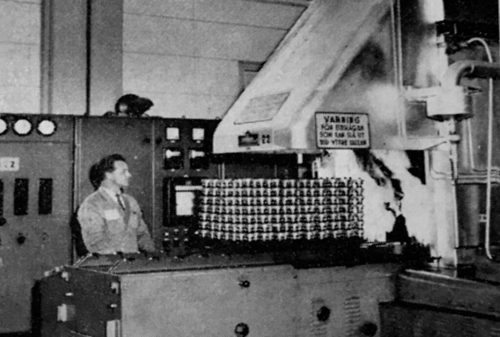
To achieve this, components are case hardened -alternatively hardened by induction current * – where the component is heated in an oven to a temperature of ca. 900 °C and later sprayed with a carbon releasing gas until the surface layer becomes carbonized. The hardening phase follows where components are submerged in a bath of oil and cooled to 150 -160 °C
Recently, a so-called continuous gas carbonization oven has been installed where loading and each step in the hardening process take place automatically for a duration of approximately 20 hours.
- Induction hardening means that the parts are heated by electric induction current until a set temperature is reached and flushed with cold water.
Marrying gear sets -Paired gearbox
All hardened details / components are ground to size on the areas where two surfaces meet. On cut gears the gear flanks are also ground to size to account of any changes in size that took place during the hardening process etc. This is particularly important for the engagement of 3rd and 4th gear during driving where there is a high demand for a low noise level inside the vehicle.
The entire production process culminates in a final quality check.
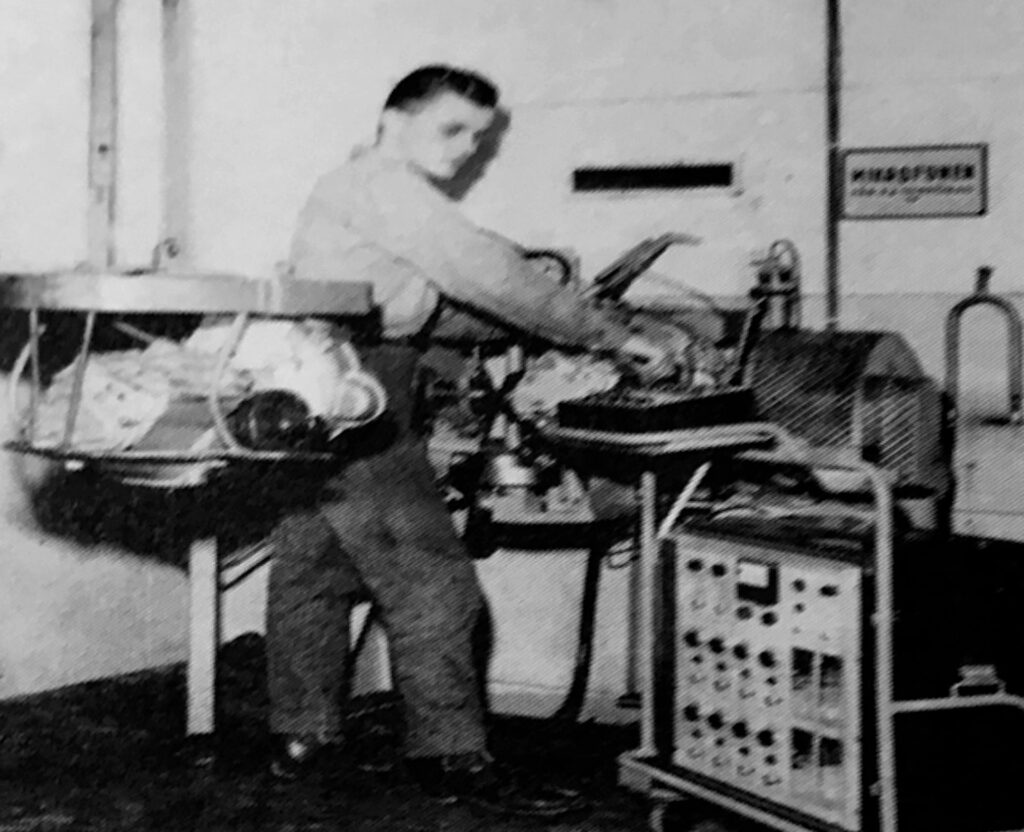
Engine and gearbox -assembly lines
The gearbox assembly starts with the assembly of the gearbox casing itself with main-shaft, lay-shafts, and gears cluster assemblies. Following this the gearboxes, differential, end casing, gear shifter turret and left and right drive hubs etc are added.
Throughout assembly random checks are frequently made of the side play of each gear cluster prior to the complete gearbox being transported on roof conveyors to the gearbox performance test cell. Each test cell is surrounded by sound-absorbing material which aides in evaluating the noise level generated from the gearbox under normal running conditions.
On each test-rig there are two disc-brakes, one connected to each drive axle from the gearbox, once connected this allows the rig operator to check variable braking forces on the gearbox etc.
An electric motor, located in an adjacent room, provides power to the test cell via an intermediate electromagnetic slip clutch -Here stepless regulation of input speed can be set.
Gearbox performance and noise level test
This test is performed at variable engine speed (rpm) and torque load settings (Nm). Noise assessment is made in relation to that generated from a master gearbox, (even measured electronically). Differential and free-wheel performance levels are also checked in connection with this test.
Gearboxes are later connected to an oil supply which also serves to flush out residues and debris from manufacture. Later the oil is drained, and the gearbox filled with normal gearbox oil prior to it being assembled with the engine.
Every gearbox is assessed for operational noise level – a ten percent check is also made of gear shifting performance along with a five percent control of the noise level generated from engaged gears and free-wheel feature.
In addition, approximately one in three-hundred gearboxes are subjected to a high load endurance test cycle in special test chambers.
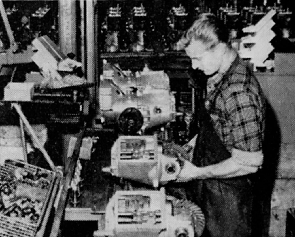
Engine assembly
Engine assembly takes place on a similar production line and starts with the assembly of the crankshaft, connecting rods etc all needing to be accurately pressed together. A particularly critical point here is the correct selection of rollers for the crank bearings. These rollers are supplied by SKF and are rated at 0.0005 mm intervals.
The crankshaft is supported in the cylinder block on ball bearings, the three connecting rods being supported on roller bearings – cleanliness is vitally important here to ensure that no impurities enter the bearing tracks themselves – and why a dust-proof transport tunnel is incorporated in transport of the engine between workstations.
Pistons corresponding to the gauged sizes specified on the cylinder block are then fitted along with the flywheel, cylinder-head and gasket, induction and exhaust manifolds, ignition distributor and carburettor.
The engines are then transported on special fixtures for further testing.
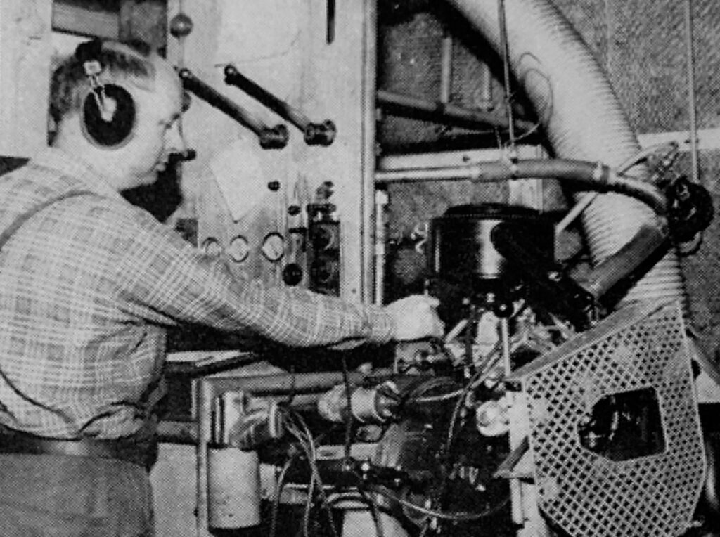
Engine testing
The test cell consists of two dynamometers-. For practical reasons, a test operator performs simultaneous tests on these dynamometers to determine each engines Power and torque ratings. To assist in evaluation noise levels the test room has been included with noise absorption panels. After an engine is secured in the test rig, it is started and run-in for a period of six minutes.
During this time, the ignition timing is adjusted, and specific fuel consumption is checked at a constant 3000 rpm.
Engine noise level is assessed prior to a final adjustment of idle rpm. All test parameters i.e., air temperature, barometric pressure etc, are recorded on each engines test report: Each engine is given a small spray of lubrication engine oil via the carburettor venturi.
Furthermore, one in every three thousand engines is selected to undergo a full engine power and performance test. All Saab Sport engines are subjected to this test.
Motor-gearbox assembly
Once assembly and testing are finalised the complete engine is fitted with all ancillary electrical equipment and following one final quality check is delivered by truck to the Saab car production facility in Trollhättan.
Currently two hundred power train units are delivered per day.